

Buying guide
How to Test Ethernet Cable
Wiremap, Split Pairs and Speed Checks
Test Ethernet cables and wall jacks, find opens, shorts and split pairs, isolate patch leads, and check link speed before replacing cable or buying a tester.
By thisMETER EditorialUpdated November 3, 20269 min read2 picks
On this page · Quick picks: buy for the question you need answered
To test an Ethernet cable, first substitute a known-good lead, then disconnect the suspect cable from network equipment and check its wiring with a tester and remote; reconnect it afterward to check the actual link. For home wiring checks, our pick is the Klein LAN Scout Jr. 2, whose wiremap includes split-pair detection. Choose the Scout Pro Max when you also need distance-to-fault or dedicated PoE testing, and keep wiring, link speed and category certification as separate results.
Quick picks: buy for the question you need answered
These recommendations follow Klein's LAN Scout Jr. 2 manual and Scout Pro Max manual.
Compare specifications and all conditions
LAN Scout Jr. 2, VDV526-200
- Wiring faults
- Opens, shorts, miswires; recognizes crossover
- Split pairs
- Explicitly supported
- Length / fault distance
- No measurement function documented
All specifications
- Powered network checks
- Unenergized cabling only
Scout Pro Max, VDV501-770
- Wiring faults
- Wiremap, opens, shorts and miswires
- Split pairs
- Not explicitly specified in the retrieved manual or product page
- Length / fault distance
- TDR measurement
All specifications
- Powered network checks
- Dedicated PoE and advertised port-speed tests; observe port restrictions
Professional qualification / certification
- Wiring faults
- Choose by the required report
- Split pairs
- Depends on instrument
- Length / fault distance
- Depends on instrument
All specifications
- Powered network checks
- Qualification asks whether cabling supports a technology; certification checks cabling standards
Full comparison table
Swipe to compare. Row labels stay visible.
| Choice | Wiring faults | Split pairs | Length / fault distance | Powered network checks |
|---|---|---|---|---|
| LAN Scout Jr. 2, VDV526-200 | Opens, shorts, miswires; recognizes crossover | Explicitly supported | No measurement function documented | Unenergized cabling only |
| Scout Pro Max, VDV501-770 | Wiremap, opens, shorts and miswires | Not explicitly specified in the retrieved manual or product page | TDR measurement | Dedicated PoE and advertised port-speed tests; observe port restrictions |
| Professional qualification / certification | Choose by the required report | Depends on instrument | Depends on instrument | Qualification asks whether cabling supports a technology; certification checks cabling standards |
Scroll horizontally to see every column
| Choice | Wiring faults | Split pairs | Length / fault distance | Powered network checks |
|---|---|---|---|---|
| LAN Scout Jr. 2, VDV526-200 | Opens, shorts, miswires; recognizes crossover | Explicitly supported | No measurement function documented | Unenergized cabling only |
| Scout Pro Max, VDV501-770 | Wiremap, opens, shorts and miswires | Not explicitly specified in the retrieved manual or product page | TDR measurement | Dedicated PoE and advertised port-speed tests; observe port restrictions |
| Professional qualification / certification | Choose by the required report | Depends on instrument | Depends on instrument | Qualification asks whether cabling supports a technology; certification checks cabling standards |
For broader tool choices, see our Ethernet cable tester comparison.
Isolate the cable before replacing anything
Cisco's troubleshooting guide recommends replacing a suspect cable with a known-good one, checking connectors and trying a known-good port. Use that as a controlled comparison: keep the devices and settings the same while changing the cable, then change the port separately. A fault that follows the cable points toward the cable path; one that stays with a port needs port or configuration investigation.
For an installed run, check the removable patch leads individually before blaming the cable in the wall. Klein specifies known-good patch leads when connecting its tester and remote to wall ports. The disconnected test path is:
Tester → checked patch lead → wall jack / installed run / patch panel → checked patch lead → test remote.
That result includes the connecting leads and terminations. If it fails, substitute a checked lead at each end and retest. Record the outlet, patch-panel position, leads and result.
Substitute
Compare the suspect path with a known-good cable and port.
Disconnect
Unplug the path from network equipment before the wiremap check.
Map
Connect the tester and its test remote; record the affected pins.
Repair and repeat
Replace the suspect lead or correct the termination, then run the same check again.
Reconnect
Check negotiated link speed and traffic separately.
Check power and plugs before connecting the tester
Inspect plugs before insertion. Klein warns that improperly terminated plugs can damage the tester's sockets; the Pro Max manual says the contacts must be recessed into the plug's plastic housing.
Run the wiremap and read the actual pins
For the LAN Scout Jr. 2, connect the cable between the main unit and its remote, turn it on, then press Test. For wall ports, use checked leads. Its display instructions put the tester-end pins on the top row and the corresponding remote-end pins directly beneath them.
Read these as illustrations of the manual's display rules, not measurements from thisMETER. In each row, compare the remote sequence with tester pins 1 2 3 4 5 6 7 8. Here, · means a blank position; – means the tester's short indication.
Normal straight-through map
- Illustrative remote row
1 2 3 4 5 6 7 8- Meaning and next action
- Each pin reaches its matching pin. Check the overall result for pair faults too.
Open pair
- Illustrative remote row
1 2 3 4 5 6 · ·- Meaning and next action
- Pins 7 and 8 have no displayed remote connection. Check those terminations and the patch leads.
Short
- Illustrative remote row
– – 3 4 5 6 7 8- Meaning and next action
- Pins 1 and 2 are shorted together. Inspect or replace the suspect lead or termination.
Reversal, a miswire
- Illustrative remote row
2 1 3 4 5 6 7 8- Meaning and next action
- Tester pin 1 reaches remote pin 2 and vice versa. Correct the reversed termination.
Split pair
- Illustrative remote row
1 2 3 4 5 6 7 8can still appear- Meaning and next action
- Continuity can look right while pair assignment is wrong. Use the split-pair result and inspect the termination scheme.
Full comparison table
Swipe to compare. Row labels stay visible.
| Result | Illustrative remote row | Meaning and next action |
|---|---|---|
| Normal straight-through map | 1 2 3 4 5 6 7 8 | Each pin reaches its matching pin. Check the overall result for pair faults too. |
| Open pair | 1 2 3 4 5 6 · · | Pins 7 and 8 have no displayed remote connection. Check those terminations and the patch leads. |
| Short | – – 3 4 5 6 7 8 | Pins 1 and 2 are shorted together. Inspect or replace the suspect lead or termination. |
| Reversal, a miswire | 2 1 3 4 5 6 7 8 | Tester pin 1 reaches remote pin 2 and vice versa. Correct the reversed termination. |
| Split pair | 1 2 3 4 5 6 7 8 can still appear | Continuity can look right while pair assignment is wrong. Use the split-pair result and inspect the termination scheme. |
Scroll horizontally to see every column
| Result | Illustrative remote row | Meaning and next action |
|---|---|---|
| Normal straight-through map | 1 2 3 4 5 6 7 8 | Each pin reaches its matching pin. Check the overall result for pair faults too. |
| Open pair | 1 2 3 4 5 6 · · | Pins 7 and 8 have no displayed remote connection. Check those terminations and the patch leads. |
| Short | – – 3 4 5 6 7 8 | Pins 1 and 2 are shorted together. Inspect or replace the suspect lead or termination. |
| Reversal, a miswire | 2 1 3 4 5 6 7 8 | Tester pin 1 reaches remote pin 2 and vice versa. Correct the reversed termination. |
| Split pair | 1 2 3 4 5 6 7 8 can still appear | Continuity can look right while pair assignment is wrong. Use the split-pair result and inspect the termination scheme. |
Klein's example combines the short on 1–2 with an open on 7–8; the table separates them to explain each indication. Open and short indications take precedence over miswires on this tester, so correct the reported fault and repeat the test before declaring the rest sound.
A crossover is a separate case. The Jr. 2 can show Pass and X-Over for a correctly wired crossover. That is not the reversed pair illustrated above. Check whether the cable is intended to be straight-through before changing it; a Pass icon alone does not answer that question.
For intermittent wiring, the Jr. 2's default Loop Mode repeats the test every 2 seconds. Use it to watch whether the map changes while checking a suspect connection. A steady pass still only covers what this instrument checks.
Why split pairs fool a basic continuity test
Ethernet pair groups are 1–2, 3–6, 4–5 and 7–8. They are not simply adjacent pins throughout the connector. Fluke Networks' split-pair explanation shows why: the pair on 4–5 sits inside the pair on 3–6.
If someone instead puts intact physical pairs on 1–2, 3–4, 5–6 and 7–8 at both ends, every conductor can reach its matching pin, yet the middle pairs are split. Fluke explains that this creates crosstalk and susceptibility to interference. Repeating a continuity check cannot resolve that ambiguity; inspect and reterminate to the connector's T568A or T568B scheme, preserving the designated pairs.
The Jr. 2 explicitly checks split pairs, but Klein specifies a minimum cable length of 1.5 feet (0.5 meters) for that function. Do not treat a very short lead's clean result as proof that its pairs are correct. Its Shield indication concerns shield contact between the ends; it does not certify cable category.
Use distance-to-fault only when the tool supports it
The Pro Max uses TDR, and Klein makes its length accuracy conditional on the correct velocity of propagation (VoP) and consistent cable parameters. Select the cable type or enter the correct VoP before relying on a distance. The specified accuracy is ±(2% + 3 ft or 1 m); treat the displayed location as approximate.
Its manual says an open or short gets a fault indication and approximate distance. MULTI means multiple fault types, with distance to the first fault encountered: repair and retest to investigate what remains.
There is an official-source conflict: Klein's product page advertises measurement up to 2,000 ft (610 m); its manual lists data cable 0–3,000 ft (0–914 m). Those are instrument ranges, not permission to run an Ethernet link that far. The Jr. 2's 2,000 ft (610 m) maximum testable cable length is also not a length readout.
Reconnect and check link speed, then traffic
Remove the tester and remote, reconnect the network equipment, and read the negotiated Ethernet speed. TP-Link's instructions give these routes:
- Windows: press Windows + R, run
ncpa.cpl, right-click the Ethernet adapter and open Status. - Mac: open System Settings → Network → Ethernet → Details → Hardware.
That speed describes the connection between the adapter and the router or switch port. It is not an Internet speed result. The Pro Max's 10/100/1G/10GBASE-T indication is different again: Klein calls these advertised speeds. Neither reading is a cable certification.
Working at 100 Mbps but failing at Gigabit? Fluke Networks identifies 1–2 and 3–6 as the pairs required for 100BASE-TX; 1000BASE-T requires all four pairs. Investigate opens on 4–5 or 7–8, while also checking port capabilities and configuration. The slower link is a clue, not a diagnosis.
For a traffic check, use wired computers on the local path and compare the suspect cable with the known-good setup. ESnet's iperf3 documentation specifies a server and client. With iperf3 installed, run this on the server:
iperf3 -s
On the other computer, replace SERVER_IP with the server's local Ethernet address:
iperf3 -c SERVER_IP
iperf3 -c SERVER_IP -R
The second command reverses traffic direction. Ensure the test uses Ethernet rather than an alternate wireless path. Compare results in both directions; iperf3 measures throughput across the setup, and ESnet notes that CPU limits can affect throughput. There is no universal application-throughput number here that certifies a cable.
If link drops or errors persist, compare port error counters as well. Cisco warns that a link light can coexist with cable damage, and that data-link errors can also come from duplex mismatch, ports or network-adapter issues. Avoid replacing installed cable solely because an Internet speed test is slow.
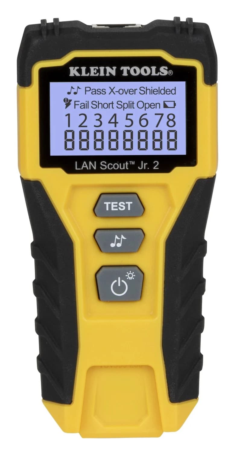
Best for home wiring checks: Klein LAN Scout Jr. 2
Klein Tools
A pocket tester for unenergized RJ45 cabling with a backlit LCD wiremap and a self-storing remote that finds opens, shorts, miswires, split pairs and shield faults, with a tone generator for tracing.
Check package and model options
Choose it for disconnected RJ45 runs when pin mapping and explicit split-pair detection answer the job. Its backlit display and included self-storing test remote make it our home pick; length measurement and active PoE diagnostics are not documented functions.
Check the variant: VDV526-200 is the tester with remote and batteries. VDV999-200 is a replacement remote, not a complete tester. Tracing also needs the separately sold VDV500-123 probe, according to Klein's product page.
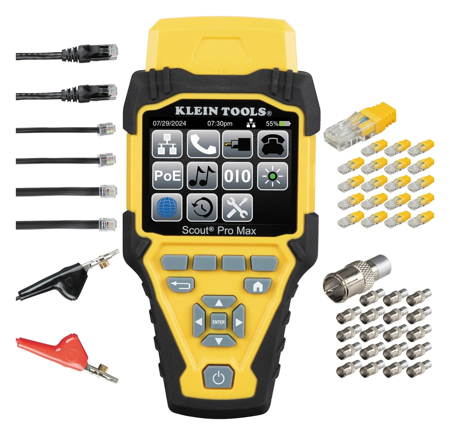
Best for locating faults and checking PoE: Klein Scout Pro Max
Klein Tools
A color-screen voice, data and video cable tester that maps RJ45, RJ11/12 and coax wiring, measures cable length with TDR, identifies up to 20 locations, tests PoE and reports advertised link speed.
Check package and model options
- IEEE 802.3af/at/bt PoE (Types 1-4); 10/100/1G/10GBASE-T link speeds
Choose VDV501-770 when TDR fault location or dedicated PoE checks will change your next action. Its manual specifies 802.3af/at/bt, Types 1–4, plus passive PoE to 60 V. Klein also lists storage for 200 test results. Buy it for those functions; do not infer qualification from its advertised-speed display.
Check the remotes: use the self-storing Test + Map remote for wiremap testing. The included 20 RJ45 LanMap and 20 coax CoaxMap location remotes identify runs; Klein says they cannot perform wiremap or length tests. VDV770-770 is a replacement test remote. The VDV500-223 tracing probe is sold separately.
For model upgrade decisions, see Scout Pro 3 vs Scout Pro Max.
Buying guide: know when to stop troubleshooting
Fluke Networks distinguishes verification, qualification and certification. Use that distinction to choose the next step:
- Yes: Verification: wiring connectivity within the tester's capabilities
- Partly: Qualification: suitability for a specified network technology, with a qualification instrument
- No: A wiremap pass is not a category compliance report
- Yes: Certification: comparison with cabling standards, using a certification instrument
For a faulty removable cord, replacement followed by the same checks is a sensible stopping point. For installed wiring that passes wiremap but remains unreliable, arrange qualification or certification before paying for a new cable pull. For contracted category compliance or a manufacturer's cabling warranty, request the appropriate certification report rather than a photo of a continuity pass.
How we choose
These are research-based recommendations, without physical product testing. We checked Klein's official product pages and manuals, Fluke Networks' fault explanations and test-tier definitions, Cisco's troubleshooting guidance, TP-Link's link-speed instructions and ESnet's software documentation on November 2, 2026. The maps are teaching examples. Our measurement policy explains how specifications differ from our own readings.
Verdict
Start with a known-good cable and port, check disconnected wiring, then check the restored link. The LAN Scout Jr. 2 is our pick for home wiremaps and split pairs; the Scout Pro Max earns the upgrade when distance-to-fault or PoE diagnostics matter. If the question is whether installed cabling meets a category standard, request certification.
Our picks at a glance
- 1
Choose for: Best for home wiring checks
Check before buying: RJ45 only: no coax or phone jacks
- 2
Choose for: Best for locating faults and checking PoE
Check before buying: A verification tool, not a certifier: it can't certify Cat 6 or 6A performance to TIA limits
Frequently asked questions
Can I test an Ethernet cable without a tester?
Start with substitution: use a known-good cable between the same devices, then try a known-good port. Cisco recommends these checks to separate cable faults from port problems. If the failure follows the cable, investigate that cable or its terminations. This narrows the problem; it does not identify individual faulty pins or certify the cable's category.
Why does my cable work at 100 Mbps but not Gigabit?
Fluke Networks explains that 100BASE-TX needs the pairs on pins 1–2 and 3–6, while 1000BASE-T needs all four pairs. Faults on 4–5 or 7–8 can therefore leave a cable suitable for the slower service. Check every pair, but also check device capabilities and port configuration: a slower link alone does not establish a cable fault.
Does a passing cable tester prove Cat 6 or 10 Gbps?
A wiremap pass establishes wiring continuity within that tester's capabilities. Fluke Networks distinguishes this verification from qualification for a network technology and certification against cabling standards. The Scout Pro Max reports advertised port speeds; that is a different result again. For a category compliance report, arrange certification using the correct test configuration and limits.
Can I test an Ethernet cable with a multimeter?
A continuity check can help investigate an open conductor on a disconnected cable, but it cannot establish correct twisted-pair assignment. That limitation follows from Fluke Networks' split-pair explanation: conductors can connect pin to pin while belonging to the wrong pairs. For this task, choose a cable tester that explicitly detects split pairs.
Related guides
Comparison · Cable Testers
Klein Scout Pro 3 vs Scout Pro Max: Upgrade or Keep Your Tester?
Keep your Klein Scout Pro 3 or upgrade? Compare kits, PoE, fault distance, switch-port information, reports and remote compatibility before buying a tester.
Buying guide · Cable Testers
HDMI Cable Testers: Continuity, Certification and What to Buy
Choose HDMI cable testers for wiring faults, compare Jonard HDMI-100 and Goobay 31961, check certification labels, and know when replacing a cable makes sense.
Best picks · Cable Testers
USB Cable Testers: E-Markers, Wiremaps and Real Speed Checks
Choose a USB cable tester for continuity, e-markers or resistance. Compare Treedix models, reuse a KM003C, and check real transfer speed with your computer.