Buying guide
How to Use a Multimeter: Continuity, Voltage and Current, Step by Step
How to use a multimeter safely: what the dial symbols mean, which jack the red lead goes in, and step-by-step continuity, battery voltage and current checks.
By thisMETER EditorialUpdated November 2, 202613 min read3 picks
Our picks at a glance
- See on Amazon1
A first meter
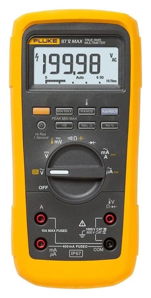
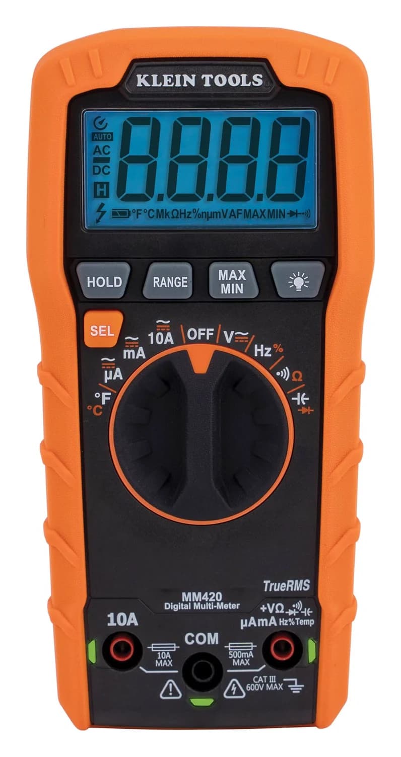
Klein Tools MM420 Auto-Ranging True RMS Digital Multimeter (600V)600V max · 10A max · 4000 counts · CAT III 600V
- See on Amazon2
A pocket meter for basic checks
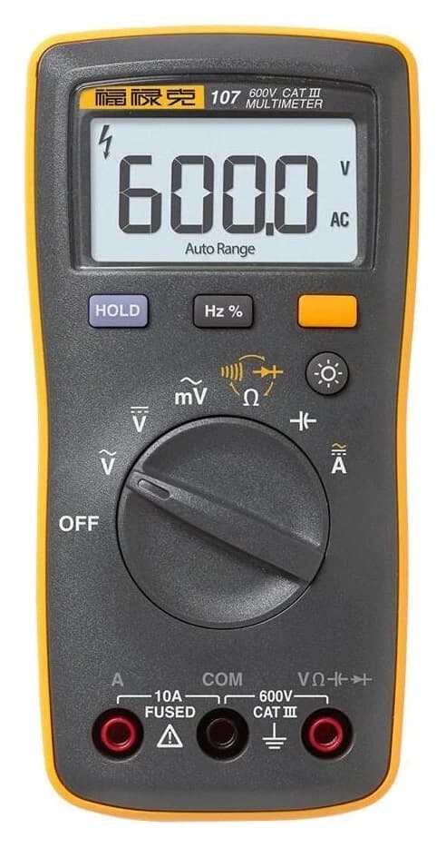
Fluke 107 Pocket Digital Multimeter600V max · 10A max · 6000 counts · CAT III 600V
- See on Amazon3
The electrician's meter
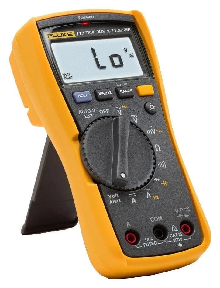
Fluke 117 Electrician's True RMS Multimeter with Non-Contact Voltage600V max · 10A max · 6000 counts · CAT III 600V
A multimeter does three everyday jobs: continuity (is this fuse or wire unbroken?), voltage (how charged is this battery?) and current (how much is this circuit drawing?). Each one starts the same way: black lead in COM, red lead in the jack that matches the dial, and, for continuity and resistance, the power off. If you're choosing a first meter, Klein's MM420 lights up the jacks each function needs, which takes the guesswork out of that step. Procedures from Fluke's and Klein's manuals and how-to guides, and East Penn's battery chart, checked November 1, 2026.
This guide sticks to low-voltage work: fuses, wires, switches, batteries and small battery-powered circuits. Household outlets and panels are a different matter, covered in the warning near the end.
- COMWhere the black lead goes, for every measurement
- < 20 ΩWhen the Fluke 117 beeps for continuity (the Klein MM420: under 50 Ω)
- 10 AThe top current range on both the Fluke 117 and the Klein MM420
The dial, the jacks and the display
| You'll see | It means |
|---|---|
| ∿ V | AC volts |
| ⎓ V | DC volts (batteries, car electrics, USB) |
| mV | Millivolts |
| Ω | Resistance |
| Continuity (beeper) symbol | Beeps when there's a complete path; often shares a dial position with Ω |
| →| | Diode test |
| F | Capacitance |
| A, mA, µA | Current: amps, milliamps, microamps |
| COM | "Common": the black lead's jack, for every measurement |
| OL | Over the range: on continuity or resistance, usually an open circuit |
| – before a reading | The leads are reversed on a DC measurement |
The jacks matter more than the dial. Fluke's guide to multimeter dials and jacks puts it bluntly: "the input jack chosen for the red test lead MUST match the parameter selected on the dial," and if it doesn't, "the meter, equipment, and technician are all at risk." The usual layout is COM for the black lead, V/Ω for the red lead when measuring voltage, resistance, continuity and diodes, and A for current up to 10 A, plus, on some meters, a separate mA/µA jack.
Meters differ, so read yours. Klein's MM420 measures milliamps and microamps through its VΩ jack and switches to its 10A jack above 400 mA. The Fluke 117 has no milliamp or microamp ranges at all; its smallest current step is 1 mA. Two helpers stop mistakes: the MM420's Lead Alert LEDs light the jacks the selected function needs, and the Fluke 117 briefly shows "LEAd" and beeps when you turn the dial to or from an amps position.
Tap a label to explore. You can also hover or use your keyboard.
Fluke 117 exampleMatch the jack and dial
This example uses the Fluke 117's A, COM and V inputs. The jack chosen for the red lead must match the selected measurement.
Sources: 1: The Fluke 117 is one of the models covered by this manual., 2: The manual identifies A as the current input on the 117 and COM as the return for all measurements., 3: The V input is for voltage, continuity, resistance and the other listed functions., 10: The red lead jack must match the selected dial function; voltage requires the voltage jack rather than the current jack.Black leadCOM: common return for all measurements
The black test lead goes in COM. COM is the common return terminal for all measurements.
Sources: 2: The manual identifies A as the current input on the 117 and COM as the return for all measurements., 4: COM takes the black test lead for all measurements.Red lead in VVoltage, continuity and resistance
The V terminal supports voltage, continuity and resistance measurements. Match the selected dial function to the red lead jack.
Sources: 3: The V input is for voltage, continuity, resistance and the other listed functions., 10: The red lead jack must match the selected dial function; voltage requires the voltage jack rather than the current jack.Continuity and resistanceDisconnect power; discharge high-voltage capacitors
Disconnect circuit power and discharge all high-voltage capacitors before testing resistance or continuity.
Sources: 6: Before resistance or continuity tests, disconnect power and discharge high-voltage capacitors.Red lead in ACurrent: check fuse, dial and range
Put the red lead in A for current measurement. Check the fuse and use the proper terminals, switch position and range before testing.
Sources: 5: The A input takes the red lead for current measurements., 7: Check the fuse and choose the proper terminals, switch position and range before current measurement.Current path in seriesPower off, break, insert meter, power on
Turn circuit power off and break the circuit. Insert the meter in series before turning circuit power on.
Sources: 8: Current measurement requires power off, a break in the circuit and the meter in series before restoring power.Never connect A acrossNo parallel probing in a current jack
Never place probes in parallel across a circuit or component while the leads are plugged into the A terminals.
Sources: 9: Never place the probes in parallel across a circuit or component while the leads are in the A terminals.Return red lead to VBefore the next voltage measurement
For voltage, put the red lead back in the voltage jack and match the dial. Do not leave it in the current jack.
Sources: 10: The red lead jack must match the selected dial function; voltage requires the voltage jack rather than the current jack.Conceptual function map; marker positions are not a socket layout. Read the markings and manual on your own meter.
Source notes10 references
The Fluke 117 is one of the models covered by this manual.
media.fluke.com — source for The Fluke 117 is one of the models covered by this manual.110/113/114/115/117 Users Manual
The manual identifies A as the current input on the 117 and COM as the return for all measurements.
media.fluke.com — source for The manual identifies A as the current input on the 117 and COM as the return for all measurements.Input terminal for measuring ac and dc current to 10 A. 115, 117 Common (return) terminal for all measurements.
The V input is for voltage, continuity, resistance and the other listed functions.
media.fluke.com — source for The V input is for voltage, continuity, resistance and the other listed functions.Input terminal for measuring voltage, continuity, resistance, capacitance, 110, 113, 114, 115, 117 frequency and testing diodes.
COM takes the black test lead for all measurements.
www.fluke.com — source for COM takes the black test lead for all measurements.COM Black test lead input for: All measurements.
The A input takes the red lead for current measurements.
www.fluke.com — source for The A input takes the red lead for current measurements.A (amps) Red test lead input for: Current ( I ) measurements of up to 10 A.
Before resistance or continuity tests, disconnect power and discharge high-voltage capacitors.
media.fluke.com — source for Before resistance or continuity tests, disconnect power and discharge high-voltage capacitors.disconnect circuit power and discharge all high-voltage capacitors before testing resistance, continuity, diodes, or capacitance.
Check the fuse and choose the proper terminals, switch position and range before current measurement.
media.fluke.com — source for Check the fuse and choose the proper terminals, switch position and range before current measurement.Check the Meter's fuse before testing. See Testing the Fuse (115, 117). • Use the proper terminals, switch position, and range for your measurement.
Current measurement requires power off, a break in the circuit and the meter in series before restoring power.
media.fluke.com — source for Current measurement requires power off, a break in the circuit and the meter in series before restoring power.1. Turn circuit power off. 2. Break the circuit 3. Insert the Meter in series with the circuit, and then turn circuit power on.
Never place the probes in parallel across a circuit or component while the leads are in the A terminals.
media.fluke.com — source for Never place the probes in parallel across a circuit or component while the leads are in the A terminals.Never place the probes in parallel with a circuit or component when the leads are plugged into the A (Amps) terminals.
The red lead jack must match the selected dial function; voltage requires the voltage jack rather than the current jack.
www.fluke.com — source for The red lead jack must match the selected dial function; voltage requires the voltage jack rather than the current jack.Important: The input jack chosen for the red test lead MUST match the parameter selected on the dial. Dial set on AC Volts? Make certain the red test lead is plugged into the jack designated for voltage (V) and not current (I).
Before any measurement
Check the meter and the leads
Fluke and Klein both say to measure a known voltage first to make sure the meter works. Don't use damaged leads: Fluke's lead check is the resistance setting with the probe tips touching, where good leads read about 0.5 Ω or less, wiggled to catch intermittent faults.
Match the rating, leads included
Klein says to use only CAT III or CAT IV rated leads with the MM420, and Fluke says never to exceed the category rating of the lowest-rated part: meter, probe or accessory.
Black lead on first, off last
Fluke's manual: connect COM before the live lead, and remove the live lead first.
Power off for continuity and resistance
Fluke says to disconnect power and discharge high-voltage capacitors first; Klein says never measure resistance or continuity on a live circuit.
How to test continuity: a fuse, a wire or a switch
Continuity answers "is there a complete path?" with a beep, so you can keep your eyes on the probes. It's how you check a fuse, a cable or a switch.
Power off and isolate the part
De-energize the circuit. Fluke says the component should be isolated from other components, so take the fuse out or disconnect the wire first.
Set up the meter
Black lead in COM, red in VΩ, dial to continuity. On many meters it shares a position with Ω: the MM420 starts in continuity there, and some meters need a button press.
Check the setting
Touch the probe tips together: the meter should beep. With the probes apart it may show OL.
Probe the part
One probe on each end. Fluke says which lead goes where is arbitrary.
Read the result
A beep means a complete path; no beep (and OL) means it's open. Fluke's guide says a good fuse should show continuity.
Where's the line between a beep and silence? It's set by the meter, and it's forgiving: Fluke notes some meters beep with up to 15 Ω in the test leads alone. The Fluke 117 manual turns the beeper on below 20 Ω and off above 250 Ω, the Klein MM420 manual beeps below 50 Ω, and Fluke's continuity guide says a meter on a 400.0 Ω range typically beeps at 40 Ω or less. So a beep means "low resistance," not zero. When the actual value matters, Fluke says to use the resistance (Ω) function instead.
How to measure DC voltage: a battery
Turn the dial to DC volts
Look for ⎓ V. If you're unsure between millivolts and volts, Fluke says start with volts. On the MM420 the V position starts on AC: press SEL for DC.
Plug in the leads
Black in COM, red in VΩ.
Touch black to negative, red to positive
On a battery, red to + and black to −.
Read the display
A minus sign means the leads are reversed, which a modern digital meter simply shows. A few millivolts with the leads apart is normal noise, per Klein.
Remove the leads
Red first, then black.
For an AA, AAA or 9 V battery, compare the reading with the voltage printed on it. A car battery takes a few more precautions, and the reading means more if you know the battery type.
A car battery, safely. Fluke's battery guide warns that lead-acid batteries "can emit explosive gas and contain acid," and battery maker East Penn says to wear proper eye protection. Turn off all accessories, keep your hands clear of fan belts and moving parts, and if the car was just driven, Fluke suggests turning the headlights on for about a minute, then off, to remove surface charge. Then measure across the terminals, red on +, black on −.
East Penn's battery care brochure gives the resting (open-circuit) voltage for each state of charge, and the two common battery types differ:
| State of charge | Flooded battery | AGM battery |
|---|---|---|
| 100% | 12.6 V | 12.8 V |
| 75% | 12.4 V | 12.6 V |
| 50% | 12.2 V | 12.3 V |
| 25% | 12.0 V | 12.0 V |
Voltage shows the state of charge, not the whole story: East Penn's own test procedure follows the voltage check with a load test.
How to measure current, and why the red lead moves
To measure current, the current has to flow through the meter, so the meter becomes part of the circuit, "in series." That's why the red lead moves to a current jack, and why that jack is protected by a fuse.
Check the fuse and the range
Fluke says to check the meter's fuse before testing. Klein says not to attempt more than 10 A on the MM420.
Move the red lead to the current jack
The one your meter marks for the current you expect: on the MM420, the 10A jack above 400 mA and the VΩ jack below it; on the Fluke 117, A.
Power off and break the circuit
Fluke and Klein both start here: remove power, then open the circuit where you want to measure.
Connect the meter across the break, then power on
The meter now carries the circuit's current. Read it.
Power off, disconnect and move the red lead back
Before your next voltage reading, return the red lead to VΩ.
That last step matters because of a warning in Fluke's manual: never place the probes in parallel with a circuit or component while the leads are in the A terminals. That's exactly what happens if you forget the lead is still in the current jack and touch the probes across a battery. When a fuse does go, replace it with the exact type in the manual: for the Fluke 117, an 11 A, 1000 V fast fuse with a 17,000 A interrupt rating. Fluke warns that an inadequate fuse increases the risk of an arc explosion if voltage reaches the current jacks.
For current on household circuits, a clamp meter is the better tool: Fluke says its hinged jaw measures current without disconnecting or de-energizing the circuit. See our clamp meter guide.
CAT ratings, in one table
The Fluke 106/107 manual defines the measurement categories printed on meters and leads:
| Category | Where it applies |
|---|---|
| CAT II | Circuits connected directly to outlets and similar points |
| CAT III | The distribution part of the building's wiring |
| CAT IV | The source of the building's low-voltage supply |
A rating only counts if every part carries it: the meter, the leads and any clips. Our multimeter guide explains how to read the category and voltage together.
What True RMS means
Fluke's True RMS explainer says an average-responding meter is accurate on a clean sine wave, but on the distorted waveforms that loads like variable-speed drives and computers create, it "can be up to 40% low or 10% high." A True RMS meter reads those correctly. For steady DC, like a battery, True RMS doesn't come into it; for AC from electronics, it matters. The Klein MM420 and Fluke 117 are True RMS; the Fluke 107 isn't.
Which meter to learn on
- Klein Tools MM420: auto-ranging and True RMS, with Lead Alert LEDs that show which jacks to use, a 400 µA range for electronics, plus temperature measurement.
- Fluke 107: a pocket meter for basic checks; not True RMS.
- Fluke 117: the electrician's meter, with AutoVolt, a low-impedance mode and VoltAlert non-contact detection, but no milliamp ranges (its smallest current step is 1 mA).
Klein Tools
Klein Tools MM420 Auto-Ranging True RMS Digital Multimeter (600V)
A 4,000-count auto-ranging True RMS multimeter rated CAT III 600V that measures up to 600 V and 10 A, plus temperature, capacitance, frequency and duty cycle.
Comes in 4 versions: see which to buy
- 600V max
- 10A max
- 4000 counts
- CAT III 600V
Fluke
Fluke 107 Pocket Digital Multimeter
A palm-size 6,000-count multimeter rated CAT III 600V that measures AC and DC voltage and current to 600 V and 10 A, plus resistance, capacitance, frequency and duty cycle; it is not True RMS.
Comes in 3 versions: see which to buy
- 600V max
- 10A max
- 6000 counts
- CAT III 600V
Fluke
Fluke 117 Electrician's True RMS Multimeter with Non-Contact Voltage
A compact 6,000-count True RMS multimeter for electricians, rated CAT III 600V, with built-in VoltAlert non-contact voltage detection, automatic AC/DC selection and a low-impedance mode.
Comes in 5 versions: see which to buy
- 600V max
- 10A max
- 6000 counts
- CAT III 600V
Our multimeter guide compares them range by range.
How this guide was made
We haven't tested these procedures on our own bench; they come from the makers. The steps follow the Fluke 110-117 and 106/107 users manuals, Klein's MM420 manual and Fluke's how-to guides on continuity, DC voltage and batteries, and the battery chart is East Penn's, all read November 1, 2026. Our method is on How we choose, and what each reading means is on How we measure.
The short version
Black lead in COM, red lead in the jack that matches the dial, power off for continuity and resistance. Continuity beeps for a complete path (below 20 Ω on a Fluke 117, 50 Ω on a Klein MM420). DC volts on a battery: red on +, black on −, and read a car battery against its maker's chart for its type. Current goes through the meter, in series, with the red lead in the current jack: move it back before you measure voltage again. And leave live mains to the meter's manual and panels to an electrician.
Frequently asked questions
What does OL mean on a multimeter?
OL means the reading is beyond what the meter can show on that setting. On continuity or resistance it usually means an open circuit: Fluke notes the display may show OL with the probes apart, and Klein's MM420 manual says O.L. is normal with open leads or a failed resistor. On a voltage or current setting, treat OL as an overload: stop and choose a higher range or the right function.
Why doesn't my multimeter beep on continuity?
Either the path is open or its resistance is above the meter's beep threshold, which varies by model: the Fluke 117 beeps below 20 Ω and the Klein MM420 below 50 Ω. Check the setting first by touching the probe tips together, which should beep. Some meters share the continuity position with resistance and need a button press to switch to the beeper.
Why did my multimeter's fuse blow?
The fuse protects the current jacks and blows when they carry too much, for example if the probes touch across a voltage while the red lead is still in a current jack, which Fluke's manual says never to do. Replace it only with the exact fuse the manual specifies: for the Fluke 117, an 11 A, 1000 V fast fuse. Fluke warns that an inadequate fuse raises the risk of an arc explosion.