

Buying guide
How to Test Continuity With a Multimeter
Fuses, Wires and Switches
Test fuses, wires and switches with a multimeter. Read OL, account for lead resistance, find intermittent breaks and compare model-specific beep thresholds.
By thisMETER EditorialUpdated November 3, 20268 min read3 picks
On this page · Quick picks and beep thresholds
To test continuity with a multimeter, disconnect power, isolate the component, put black in COM and red in VΩ, then select audible continuity and touch the probes across the part. A beep means resistance is below that meter's threshold; read the resistance too, because a tone does not mean zero ohms. If you need a first meter, our pick is the Klein Tools MM420 for its illuminated jack guidance and default continuity mode. Setup source: Fluke.
Quick picks and beep thresholds
Keep your existing meter if its continuity or resistance function works. These are conditional buying picks; the threshold is a setting to understand, not a quality score.
Compare specifications and all conditions
Klein MM420
- Our pick for
- A first meter
- Selecting continuity
- Continuity/resistance dial position; continuity is the default
- Manufacturer's beep threshold
- Below 50 Ω
All specifications
- Buying caveat
- Lead-Alert helps with jack placement; still check the display icon
Fluke 107
- Our pick for
- A pocket option
- Selecting continuity
- Resistance position, then yellow button once
- Manufacturer's beep threshold
- Below 70 Ω
All specifications
- Buying caveat
- Compact, backlit and supplied with SmartStrap; a tone can still accompany nonzero resistance
Innova 3340
- Our pick for
- Wider automotive work
- Selecting continuity
- Shared resistance/diode/continuity position; select the continuity icon with SEL
- Manufacturer's beep threshold
- Below 120 Ω in the older Rev. B instructions; match the manual to your unit
All specifications
- Buying caveat
- Buy for RPM, dwell and pulse width, rather than continuity alone
Full comparison table
Swipe to compare. Row labels stay visible.
| Meter | Our pick for | Selecting continuity | Manufacturer's beep threshold | Buying caveat |
|---|---|---|---|---|
| Klein MM420 | A first meter | Continuity/resistance dial position; continuity is the default | Below 50 Ω | Lead-Alert helps with jack placement; still check the display icon |
| Fluke 107 | A pocket option | Resistance position, then yellow button once | Below 70 Ω | Compact, backlit and supplied with SmartStrap; a tone can still accompany nonzero resistance |
| Innova 3340 | Wider automotive work | Shared resistance/diode/continuity position; select the continuity icon with SEL | Below 120 Ω in the older Rev. B instructions; match the manual to your unit | Buy for RPM, dwell and pulse width, rather than continuity alone |
Scroll horizontally to see every column
| Meter | Our pick for | Selecting continuity | Manufacturer's beep threshold | Buying caveat |
|---|---|---|---|---|
| Klein MM420 | A first meter | Continuity/resistance dial position; continuity is the default | Below 50 Ω | Lead-Alert helps with jack placement; still check the display icon |
| Fluke 107 | A pocket option | Resistance position, then yellow button once | Below 70 Ω | Compact, backlit and supplied with SmartStrap; a tone can still accompany nonzero resistance |
| Innova 3340 | Wider automotive work | Shared resistance/diode/continuity position; select the continuity icon with SEL | Below 120 Ω in the older Rev. B instructions; match the manual to your unit | Buy for RPM, dwell and pulse width, rather than continuity alone |
Thresholds come from the Klein manual, Fluke 106/107 manual and Innova Rev. B manual. Innova's specification table calls its threshold approximately 120 Ω or less, while its procedure says less than 120 ohms: treat it as approximate, not a precise boundary.
Start with an isolated, unpowered component
Work on a removed fuse, a disconnected loose wire or an isolated mechanical switch. Disconnect the equipment's power source and discharge capacitors by its maker's procedure; confirm voltage is absent before selecting continuity. Fluke says continuity testing is only for circuits without voltage. Safety source.
For vehicles, follow the service manual's isolation procedure. Fluke warns that improper probing can damage sensitive modules. Automotive guidance.
Select the function and prove the leads
Inspect the leads for cracked insulation or damaged connectors. Use the jacks and continuity icon specified by your manual: the Ω dial position may share functions, so selecting Ω alone may leave the sound disabled. Keep the red lead out of a dedicated current input for this test. Lead inspection, function selection.
Touch the probe tips together: expect a tone in continuity mode and a low reading. Separate them: expect OL or your manual's open-circuit indication. In resistance mode, record the shorted-lead baseline. Fluke describes typical lead resistance as 0.2–0.5 Ω; it advises troubleshooting good-quality leads reading above about 0.5 Ω. Resistance guidance, lead check.
Isolate
Disconnect power, safely discharge stored energy and separate the part from other circuit paths.
Connect
Black lead to COM; red lead to VΩ, following the manual.
Select
Choose audible continuity and confirm its display icon.
Prove
Touch tips together, then separate them; check the low-reading and open-path responses.
Record
Note shorted-lead resistance, then measure the isolated part and record both sound and display.
If the leads fail this check, fix that before condemning a component. Need help with dial markings? Use our general multimeter tutorial.
Test a removed fuse
With power disconnected, remove the fuse from its holder. On a cartridge fuse, touch a probe to each metal end cap; on a blade fuse, touch the separate metal blades. Hold steady contact. An intact fuse should beep and show low resistance; persistent OL suggests an open fuse. The plastic or glass body is not a test terminal. Fuse procedure.
If OL appears, reseat the probes and repeat the shorted-tip check before recording an open fuse. Inspect it too: Fluke notes that a fuse can look intact despite an internal fault. Avoid diagnosing it while connected to other circuit paths; see the parallel-path explanation below.
Trace a loose wire and an intermittent break
Disconnect the wire at both ends and identify the same conductor at each end from the equipment wiring diagram. Put a probe on each exposed terminal of that conductor. A stable beep with low resistance supports a continuous path. OL means you should check terminal contact and conductor identification before recording an open path. End-to-end procedure.
Keep the probes stationary and gently flex the wire, especially near its terminations. If the tone breaks or the display changes to OL, record the position that causes it; then repeat while keeping probe contact steady. Fluke recommends moving wires during testing to reveal intermittent faults. Check the meter leads separately if the symptom follows their movement. Wire movement, intermittent test leads.
Test a simple mechanical switch in both positions
Isolate the switch and identify the contact pair from its maker's diagram. For a simple on/off contact pair, probe across those terminals while operating the switch: the open position should give OL and no tone; the closed position should give a low resistance reading and a tone. Compare the closed reading with your lead baseline. Switch principle, contact resistance.
If it beeps in both positions, revisit the terminal diagram and isolation. If it stays open in both, repeat the lead and contact checks. Use the manufacturer's diagnostic procedure for electronic controls.
Copy this fault-isolation worksheet
Record meter/model and manual revision: ___; selected mode: ___; shorted-lead resistance: ___ Ω. Fill the blanks with your results against these expected patterns.
Removed fuse, metal end to metal end
- Expected pattern
- Tone and low resistance
- Record
- Sound ___; Ω/OL ___
- If it differs
- Recheck contact; persistent OL indicates open fuse
Loose wire, same conductor end to end
- Expected pattern
- Stable tone and low resistance
- Record
- Stationary ___; while flexed ___
- If it differs
- Hold probes steady and localize the movement causing the change
Mechanical switch, open position
- Expected pattern
- No tone; OL
- Record
- Position ___; display ___
- If it differs
- Recheck chosen terminals and parallel paths
Same switch terminals, closed position
- Expected pattern
- Tone and low resistance
- Record
- Position ___; Ω ___
- If it differs
- Recheck leads and contact, then compare with maker's limit
Full comparison table
Swipe to compare. Row labels stay visible.
| Isolated test | Expected pattern | Record | If it differs |
|---|---|---|---|
| Removed fuse, metal end to metal end | Tone and low resistance | Sound ___; Ω/OL ___ | Recheck contact; persistent OL indicates open fuse |
| Loose wire, same conductor end to end | Stable tone and low resistance | Stationary ___; while flexed ___ | Hold probes steady and localize the movement causing the change |
| Mechanical switch, open position | No tone; OL | Position ___; display ___ | Recheck chosen terminals and parallel paths |
| Same switch terminals, closed position | Tone and low resistance | Position ___; Ω ___ | Recheck leads and contact, then compare with maker's limit |
Scroll horizontally to see every column
| Isolated test | Expected pattern | Record | If it differs |
|---|---|---|---|
| Removed fuse, metal end to metal end | Tone and low resistance | Sound ___; Ω/OL ___ | Recheck contact; persistent OL indicates open fuse |
| Loose wire, same conductor end to end | Stable tone and low resistance | Stationary ___; while flexed ___ | Hold probes steady and localize the movement causing the change |
| Mechanical switch, open position | No tone; OL | Position ___; display ___ | Recheck chosen terminals and parallel paths |
| Same switch terminals, closed position | Tone and low resistance | Position ___; Ω ___ | Recheck leads and contact, then compare with maker's limit |
Finish with isolation points: ___; probe locations: ___; next action: ___. Retest after correcting contact or isolation. Fluke's linked fuse and automotive procedures recommend documenting results.
Why a beep can mislead
Parallel paths: the meter reads every available path between its probes. A connected circuit can therefore provide a conducting route around the part you meant to test. Remove the part or disconnect the necessary connection, following its manual; on circuit boards, Fluke notes that lifting a component lead may be necessary. Parallel-path source.
Probe contact and lead resistance: dirt, oil, fingers touching probe metal and poor contact can alter readings. Make firm metal contact and keep fingers behind the guards. Use REL only if your meter supports it; otherwise retain the shorted-lead baseline alongside the component reading. Resistance source, probe handling.
Thresholds and load: continuity uses a small test current. Our inference: passing that check alone cannot establish performance under the equipment's operating load. Fluke describes voltage-drop diagnosis as a separate test under load; follow the equipment's service procedure if an apparently continuous wire still fails in use. Continuity current, voltage-drop distinction.
- Yes: A steady tone identifies resistance within the meter's audible threshold.
- Partly: No tone needs interpretation alongside the resistance display and probe contact.
- No: A tone alone does not establish zero resistance.
- No: Neither a tone nor silence establishes the absence of voltage.
Best first meter: Klein Tools MM420
Our beginner pick has Lead-Alert LEDs, a backlight and a continuity mode that is the default at the shared continuity/resistance position. Its manual specifies CAT III 600V and a below-50 Ω audible threshold. Those features make setup approachable; the tone still needs the resistance reading beside it. Klein specifications.
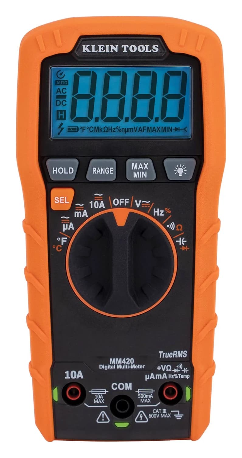
Klein Tools
A 4,000-count auto-ranging True RMS multimeter rated CAT III 600V that measures up to 600 V and 10 A, plus temperature, capacitance, frequency and duty cycle.
Check package and model options
- 600 V max
- 10 A max
- 4,000 counts
- CAT III 600V
Variant check: buy the MM420 named here. Klein marks the older MM400 as no longer in production and identifies the MM420 as its newer model. Use the manual matching the meter in your hand. MM400 status.
Best pocket option: Fluke 107
Choose this for its compact body, backlit display and included magnetic SmartStrap. To activate continuity, select resistance and press the yellow button once; the manual specifies a tone below 70 Ω. That threshold is a reason to read the display, rather than accepting every beep as an excellent connection. Product and package, manual.
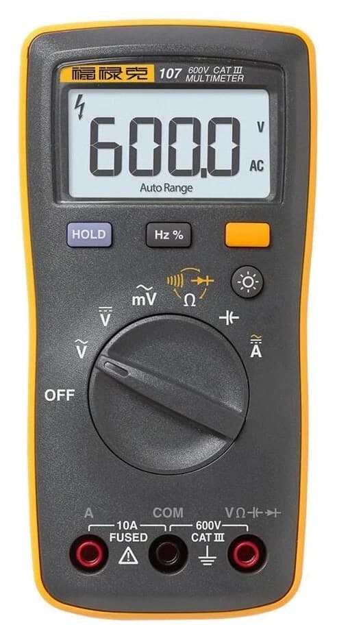
Fluke
A palm-size 6,000-count multimeter rated CAT III 600V that measures AC and DC voltage and current to 600 V and 10 A, plus resistance, capacitance, frequency and duty cycle; it is not True RMS.
Check package and model options
- 600 V max
- 10 A max
- 6,000 counts
- CAT III 600V
Variant check: the shared manual covers the 106 and 107; its diode, frequency and duty-cycle instructions identify those functions as 107-only. Do not assume every function in a shared manual applies to both models.
For wider automotive diagnostics: Innova 3340
Choose the 3340 when you also need RPM, dwell and pulse width. Innova's current page includes a temperature probe, inductive RPM clamp and case; those are the reasons for this conditional pick. Keep your existing meter for a basic fuse check. Current package.
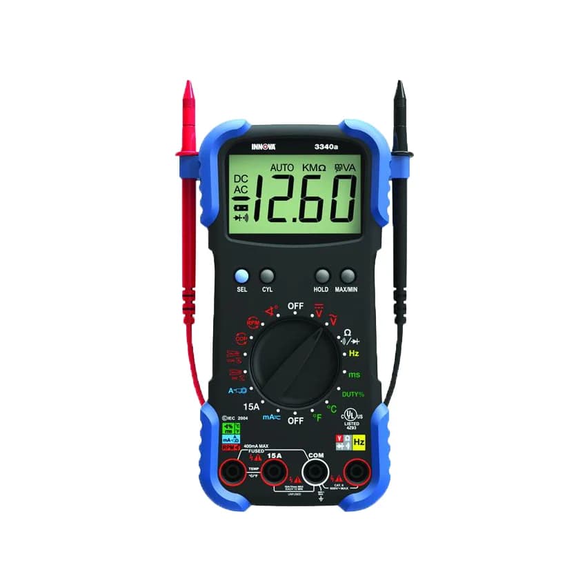
Innova
An auto-ranging automotive multimeter that adds RPM (with an inductive pickup), dwell, pulse width, duty cycle, frequency and temperature to the usual electrical tests, with a 15 A unfused current input.
- 600 V max
- 15 A max
- 4,000 counts
Documentation conflict: the older Rev. B instructions describe the thermocouple and inductive pickup as optional, whereas the current sales page includes them. Confirm the supplied accessories and matching manual before buying. That manual also excludes continuity from its MIN/MAX and HOLD functions, so do not buy it expecting those buttons to capture continuity interruptions. Rev. B instructions.
How we choose
These recommendations use official product pages and model manuals, with setup, documented beep thresholds and package contents driving the choices. They are editorial judgments from document research; no bench results are claimed. Where documents differ, the difference is identified rather than resolved by assumption. See How we choose.
Buying guide: replace only a missing function
A working resistance range can answer the basic open-path question without an audible mode. For wider choices, use our multimeter buying guide; for setup, return to how to use a multimeter.
Verdict
Start with isolation, prove the leads, and record sound and resistance. Choose the MM420 for illuminated jack guidance, the 107 for its pocket format, or the 3340 for additional automotive functions.
Our picks at a glance
- 1
Choose for: Best first meter
Limit: Lead-Alert helps with jack placement; still check the display icon
- 2
Choose for: Best pocket option
Limit: Not True RMS: Fluke positions it for jobs where True RMS accuracy isn't needed
- 3
Choose for: For wider automotive diagnostics
Limit: The official manual states measuring circuit category II without an associated CAT voltage; the complete category/voltage rating remains unconfirmed
Frequently asked questions
Does a continuity beep mean zero resistance?
No. The beeper responds below a model-specific resistance threshold. Klein specifies below 50 Ω for the MM420; the Fluke 106/107 manual specifies below 70 Ω. Neither threshold means zero resistance. For a fuse, loose wire or closed mechanical switch, also read the resistance and compare it with the shorted-lead baseline. Use the component maker's specification for an acceptance limit.
What does OL mean on a continuity test?
OL indicates an open path or resistance beyond the selected measurement range; it does not mean zero ohms. Separated probes normally show OL. Across a removed fuse, persistent OL after checking probe contact indicates an open fuse. Across an isolated switch in its open position, OL is expected. Check the meter's manual because display symbols vary.
Can I test continuity on a powered circuit?
No. Disconnect power and follow the equipment maker's procedure for safely discharging capacitors and confirming that voltage is absent before selecting continuity. The meter supplies its own test current. A continuity tone is not a voltage measurement, and silence does not establish that a circuit is safe to touch. Keep these tests to isolated, unpowered parts.
Can I check continuity without a beeper?
Yes, use the resistance function on the isolated, unpowered component. A low resistance reading supports a conducting path; OL or an overrange indication calls for checking contact and the selected range before concluding the path is open. Record the shorted-lead reading first. An audible function is convenient, but buying another meter is unnecessary when your existing resistance function can answer the question.
Related guides
Best picks · Multimeters
Best Multimeters for Electricians: LoZ, CAT Ratings and Job Fit
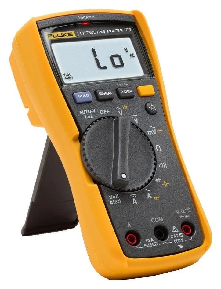
Choose an electrician's multimeter by job: Fluke 117 for branch circuits, 87V MAX for industry, Klein MM420 for extra functions, or the narrower Fluke 113.
Best picks · Multimeters
Best Multimeters for Automotive Work: Batteries, Sensors and RPM
Choose an automotive multimeter for voltage drop, sensors, RPM and small currents. Compare Klein, Innova and Fluke, kit contents and DC clamp limitations too.
Comparison · Multimeters
AstroAI DM6000AR vs KAIWEETS HT118A: Which Budget Multimeter?
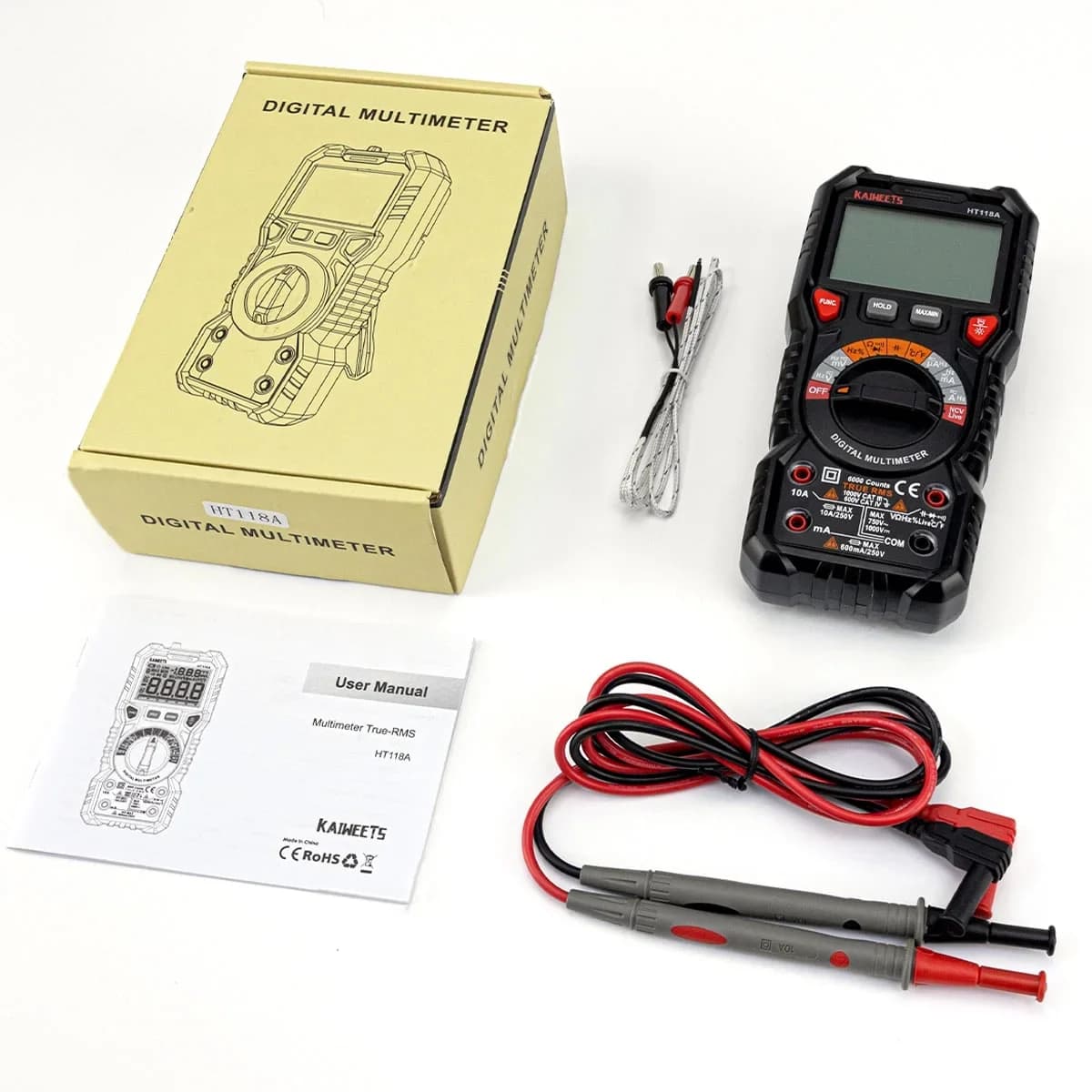
Choose an AstroAI DM6000AR or KAIWEETS HT118A for your first meter: compare controls, voltage claims, fuses, accessories and safe low-voltage starter tasks.